The Saw Carriage
The saw carriage held the log while it was being sawn. It incorporated machinery which held the log, or could move the log a “set” distance to provide various thickness’ of lumber. The early versions of the carriage were simple. The log was rolled on it, fastened, and the carriage was set in motion by a ratchet-works driven by a water wheel. Once started, the operator went to his other business until the cut was completed. He then “gigged” the carriage back by hand, used a crowbar to reset the log, and started the carriage in motion again. It was slow, but far better than sawing by hand. Later, cable, and then steam, powered the carriage.
The carriage had to be exactly positioned in relation to the head saw with the utmost care and accuracy. If the carriage was not in line at any point while the log was being sawn, the boards were uneven in thickness.
The carriage consists of a heavy wood, or metal framework, riding on several sets of trucks (wheels) and carrying two or more head-blocks. It rides on two steel rails; one flat, the other shaped with a flat crown and beveled edges. The carriage wheels are machined to a corresponding fit and the wheel diameter varied from 12 inches to 18 inches. The length of the carriage track was more than double the length of the carriage.
The outside rail is shaped, as it is desirable to carry the lighter portion of the load on that rail, to lessen wear and friction. Also, if the shaped rail faced the head saw, there was a tendency for the steam-turner to raise and derail the carriage.
Carriages are built for a large range of log diameters and lengths and their dimensions depended upon the logs cut for the mill. In special cases, they could handle logs up to 100 feet long, but if there is an intermix of lengths, there could be a trailer carriage for the longer logs. Its occurrence was infrequent, but it was a part of the mills cutting long bridge timbers. Track cleaning devices were attached to the carriage to keep the rails clear of sawdust and rubbish.
The number of trucks (wheels) under the carriage depended upon its length, and there usually were two axles under each head-block. Depending upon its length, the carriage contained two or more head-blocks; three were the average.
The head-blocks were placed across the carriage. The upright moveable portion of the head-block was the knee, and a line shaft through the head-blocks controlled the movement of the knees. The set-works were attached to this shaft.
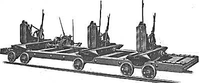
Typical Three Head-Block Saw Carriage
(The Filer & Stowell Company)
The knee is an upright, hollow, metal framework containing the log dogs, which engage and hold the log on the carriage. A hand lever engages or retracts the dogs. These consist of two sets of teeth, one pointing upward, the other downward. The motion of the lever forces the teeth into the log. On the final cut, these dogs are receded and a single board dog, top and bottom, engages the timber on the edge. Most carriage dogs were operated by hand, but electric, compressed air, and vacuum dogs have been used. If the timber is very uneven, a hammer-dog was used to hold the logs until a dogging-face was secured. Of the men who rode the carriage, one or two were the doggers. Their job was to operate the various dogs and other work assigned to them.
The set-works were incorporated into the shaft connecting the head-blocks. This mechanism advanced or retracted all knees a certain distance simultaneously. It was operated by the setter riding on the carriage, who received his instructions by hand signals from the sawyer for the width of the next cut or if the log was to be turned. The setter had a dial on the set works which he used to determine the distance to move the set-works. Set-works were operated by hand controls, although steam and electric set works are found in modern mills. Their complexity depended upon the size of the saw mill. In small operations, the setter and dogger jobs were combined in one occupation, or eliminated by set-works operated by the sawyer.
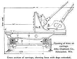
Carriage Cross Section
(Allis-Chalmers Company)
The carriage was driven by several means. The cable-feed used steel cable, the ends of which were fastened to the opposite ends of the carriage. This cable passed through idler pulleys at each end of the carriage track, and then made several turns around a grooved, power-driven drum. The speed of feed was regulated by a handle controlling the tension of a belt, between the driving pulley, and a corresponding pulley on the grooved drum. Both advancing and return movements were accomplished by this drive. There were several variations of this drive, one of which was the rack and pinion feed. Again, its speed control was by friction between belts and pulley. However, there was the severe problem of rubbish lodging between the teeth of the rack and pinion, throwing the carriage out of line.
The steam-feed was the most common in the larger mills. It consisted of a number of cast-pipe sections which could be coupled to suit the length of carriage and capped at the ends. The bore of the cylinder varied upward from 8 inches to 14 inches. Within this cylinder was a piston which was attached by a piston rod to the carriage. The cylinder was bolted to the mill floor between the tracks near the flat rail and steam port pipes were attached to each end of the cylinder from the valve chest controlled by the sawyer's lever. This lever controlled a valve which admitted steam to the cylinder in the required direction of travel and at the speed desired. The development of the steam-feed greatly increased the speed of the saw carriage and with it, a resulting increase of mill capacity. The speed earned it the name of “Shot Gun” feed, especially on the return movement. The shot gun feed was the fastest carriage return ever developed and was aptly named as the carriage was actually “blasted” back on the return movement. Today, no carriage moves that fast, for occupational safety standards would prohibit its use. In addition to the use of steam, experiments have been conducted with hydraulics and compressed air. Most modern mills utilize electric feeds.
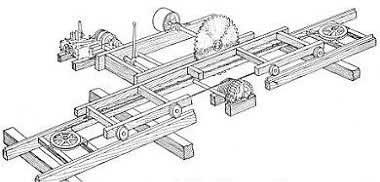
Cable Type Steam Feed Circular Saw Mill
(The American Lumberman)
The final and necessary part of the carriage was a spring or permanent bumper at the extreme ends of carriage travel. It absorbed the shock of the carriage at either end, especially on the retrograde movement, for quite often the speed of the returning carriage was misjudged and without it, the carriage could have been damaged.